CONVERTIR DE VIEILLES GUIRLANDES DE NOËL À INCANDESCENCE EN LED
Ce projet consiste à prendre des guirlandes de Noël traditionnelles à lampes à incandescence enfichables (ou « fairy lights » comme on les appelle au Royaume-Uni) et à les convertir en LED. Cela réduit considérablement leur consommation d’énergie et vous permet d’utiliser N’IMPORTE QUELLE couleur de LED que vous pouvez trouver pour créer des ensembles de lumières personnalisés. Et vous pouvez les changer pour de nouvelles LED à tout moment car elles utilisent des LED standard.
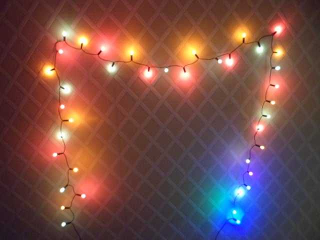
Ce projet ne convient qu’aux ensembles de lumières qui ont des lampes enfichables dont la lampe en verre n’est pas collée dans la base. L’ensemble doit avoir un câblage homologué pour le secteur pour des raisons de sécurité.
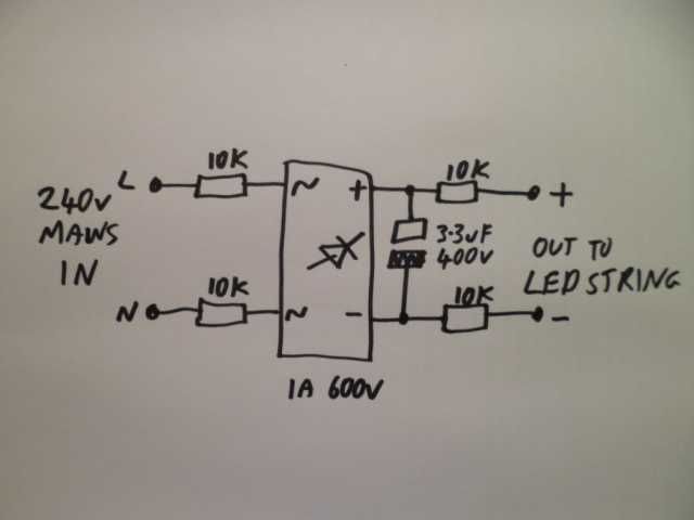
Si nous changions simplement les lampes à incandescence d’origine pour des LED, elles seraient probablement détruites presque instantanément car les LED ne conviennent qu’à un courant continu limité.
Le circuit d’alimentation illustré ci-dessus est aussi simple que possible. Il n’y a que quelques résistances pour limiter le courant et un pont redresseur pour le convertir de courant alternatif en courant continu. J’ai également montré un condensateur électrolytique dans le schéma ci-dessus et sa fonction était de réduire le léger scintillement causé par l’alimentation secteur non lissée, mais plus tard, j’ai décidé qu’il était préférable de ne pas l’utiliser car il y a une possibilité éloignée qu’il puisse tomber en court-circuit et surcharger les deux résistances entre lui et le secteur.
Les résistances sont choisies pour limiter le courant à quelques milliampères et, en tant que telles, leur puissance combinée n’a pas besoin d’être très élevée. La majeure partie de la tension d’alimentation secteur sera perdue dans les LED, le reste étant dissipé sous forme de chaleur par les résistances.
Pour une alimentation secteur de 230 V, il est préférable d’utiliser un minimum de 40 LED, ce qui entraînera généralement une chute d’environ 2,5 V chacune, soit un total d’environ 120 V. Il reste alors 110 V à faire chuter dans les résistances. J’ai utilisé quatre résistances de 10 K ohms (dix mille ohms) de quart de watt, ce qui donne un total de 40 000 ohms. Cela donne un courant théorique d’environ 3 mA, ce qui signifie que seulement 0,33 Watt est dissipé par les résistances, soit moins d’un dixième de watt par résistance.
Pour une alimentation de 120 V avec 20 LED, nous aurions environ 50 V aux bornes des LED et 70 V à faire chuter dans les résistances. Nous pourrions donc utiliser quatre résistances de 4700 ohms de quart de watt, ce qui donnerait à nouveau environ 3 mA à travers le circuit et dissiperait moins de 0,1 W sur chacune des quatre résistances.
L’utilisation de quatre résistances est pour la sécurité thermique et électrique, car la répartition de la dissipation sur quatre entraîne une chaleur plus faible (à peine la température corporelle) et les résistances multiples augmentent également leur tenue en tension combinée. Il se trouve également que le redresseur a quatre broches et qu’il est très facile de souder une résistance sur chaque broche afin qu’elles se retrouvent toutes en série avec le chemin de courant, même si cela semble un peu étrange sur le schéma.
Le redresseur doit être évalué pour au moins la tension secteur de crête. Il ne verra pas cette tension en fonctionnement normal, mais lorsque les LED sont retirées du circuit, la tension peut atteindre la tension secteur de crête. Pour une alimentation de 230 V, je recommande un redresseur évalué à 1 A 600 V et pour une alimentation de 120 V, je recommande un redresseur évalué à 1 A 200 V. La valeur nominale de 1 ampère est BIEN plus que ce qui est nécessaire, mais c’est une valeur très courante pour un redresseur. Vous pouvez fabriquer un redresseur discret à partir de quatre diodes de 1 A, mais je recommande d’utiliser un pont redresseur pour plus de simplicité.
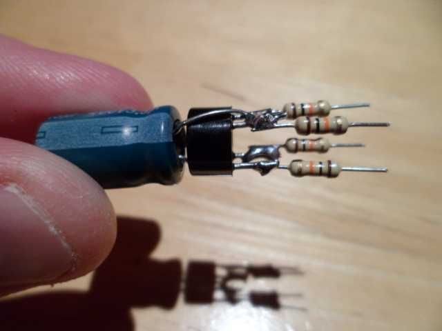
Now how simple is this? Ignore the capacitor, since it’s probably better not to use it, and the high voltage ones are quite hard to find anyway. The circuit only need the four resistors and the bridge rectifier.
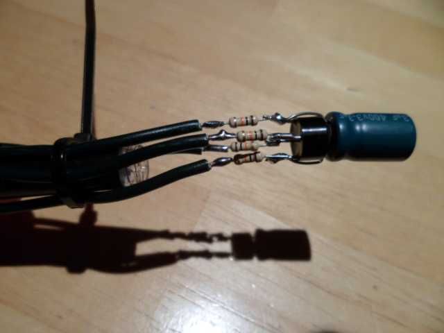
The cable on the existing tungsten string of lights is chopped about a foot (300mm) from the plug and the two wires coming from the plug are soldered to the resistors that are connected to the rectifiers AC input pins (usually marked with a small squiggle). The two wires going to the lights are connected with one going to the resistor connected to the rectifiers positive (+) pin and the other going to the resistor connected to the rectifiers negative (-) pin.
At this point it’s a good idea to mark which of the wires is connected to the positive side as that will affect the direction the LEDs are plugged into the string.
Note the use of a cable tie and pen to keep all the wires apart. This is because we are going to pot the whole assembly in fast-setting two part resin to make it electrically safe.
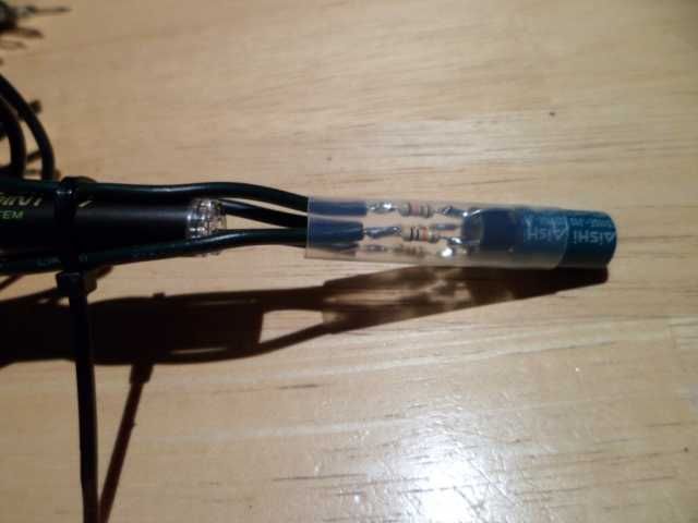
In this picture I used a bit of heatshrink sleeving to act as a potting tube, and ended up using two bits since I didn’t have one long enough to cover both the (unnecessary) capacitor and the rest of the assembly. Ideally you would find a long thin plastic sleeve or container with a closed end so that there was plenty of room to pot the circuit deeply in resin.
This is a really tricky bit as you need to keep the wires well apart but still leave room to drizzle resin in around the components.
I recommend using two-part fast setting (about 5 minutes) resin, like Araldite or the many alternatives. I tend to mix it in disposable plastic shot glasses with wooden coffee stirrers that can also be used to drizzle the resin in.
If you use a larger sleeve/cap than I did then you can fill it part-way with resin and then plunge the whole circuit into it so it flows up and around the circuitry.
The resin tends to flow well around the components but if you do use the fast setting resin you may find 5 minutes just a bit too fast. If in doubt use the slower setting resin and have patience. Resin has a knack of getting everywhere, so do the potting in a suitable work area.
If it does go wrong then just start again. The components are cheap and it’s better to end up with a safe power supply than a bodged one.
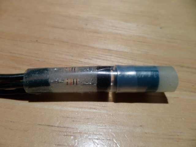
And here it is potted with the components visibly well spaced to avoid internal short circuits. The resin is acting as an insulator and modest strain relief for the wires.
Don’t plug it in at this point as the current is so low that the tungsten lamps will not even glow, and instead the resistors will be getting hotter than normal.
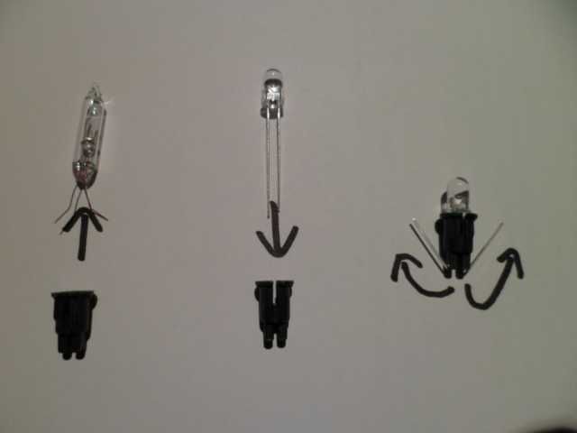
Now we start to swap the tungsten lamps for the LEDs, starting with just one. Remove the original tungsten lamp from its holder as shown and drop your choice of LED in its place. I strongly recommend the high brightness types for best effect. Push the LED fully against the front of the holder and fold the leads back along the side as shown above.
If you scavenge a highly desirable LED from somewhere and it doesn’t have long enough leads, you can solder on extension leads so it can be used.
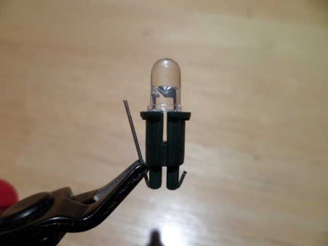
Carefully crop the bent LED leads so that they do not extend above the contact area of the base. I like to use a fine pair of snips and rest them on the ledge at an angle to get a consistent length.
If you crop them too short they may not make a reliable connection, and if you leave them too long they may prevent the LED going fully in.
IMPORTANT! Make sure no leads are left uncut as it will result in live pins sticking out of the lamp sockets when they are pushed in!
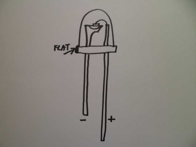
For reference MOST of the LEDs commonly available have the internal anvil shaped reflector inside them connected to the negative pin. It’s important to ensure the LEDs are inserted into the string the correct way round as putting them in the wrong way round may destroy them.
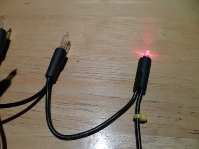
I find it best to do just a few LEDs at a time so I can see if I have put one in the wrong way round, got a faulty one or not inserted it correctly.
Note how I have marked the positive side of the string with a cable tie. All the LEDs positive connections will point towards that.
Don’t leave the set lit too long with a lot of tungsten lamps still in it, as it will make the resistors run hotter. You can see that none of the old tungsten lamps are glowing at all while the red LED is lit. This is because the super-low current the set now uses is not enough to make them glow.
Now just work your way along the set from that end changing a few lamps over at a time. It’s strangely therapeutic swapping in the LEDs.
If you wish you can make a little polarity dot on each holder to make swapping LEDs easier later on.
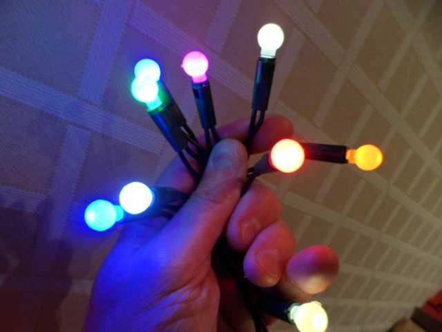
And soon you’ll have a complete string of LED lights that can be swapped about and changed as desired when you stumble across new LED styles or colours (just remember to note the polarity before swapping them). You can also scavenge press-fit caps for them from other sets. If the caps are too loose on the bare LEDs then you can add a couple of layers of clear heatshrink sleeving round the LEDs to make them a press fit. A tutti-frutti style mish-mash of random colours and caps is strangely pleasing.
If you want to make standard lens style LEDs wider viewing angle you can do so by « cracking the ice » on them. This is where you carefully crack off the end of the lens with a pair of suitable cutters. Just make sure that you don’t cut right down into the LED chip itself or expose the internal (live) metal connections. Also note that the end of the LED you’re cracking off usually shoots across the room like a ricocheting bullet! Make sure you don’t hit anyone with one! The cracked ice LEDs have a very crystalline effect that shoots the light out in all directions.
If you do use a random mix of styles and colours then you can pretty much guarantee that NOBODY ELSE in the world has a set of lights like YOURS.
And here’s the best bit…. The whole set of lights now consumes less than a single watt of power! That means the whole string uses LESS energy than just ONE of the original lamps!
If you leave them on 24/7 they will consume much less than a single dollar of electricity in a year.
The fact the LEDs are being run at a fraction of their rated current means that they will last a VERY long time without losing efficiency.